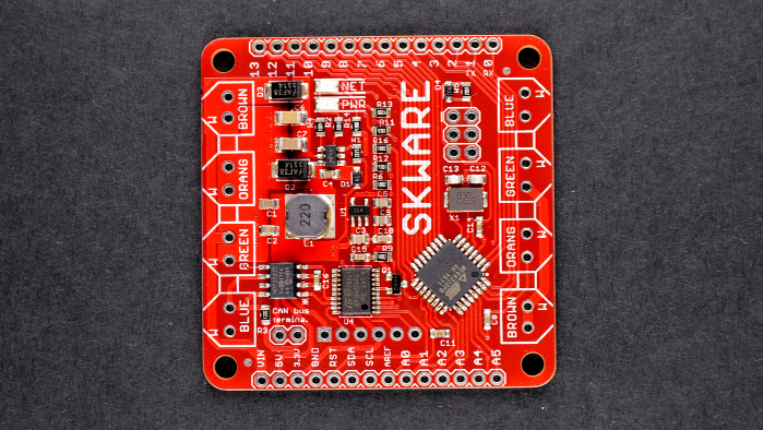
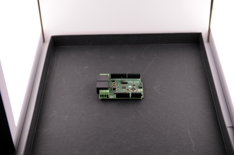
I've been taking pictures of circuits as part of the (now defunct) Omzlo One Kickstarter and ha ji won sex videothe new follow-up "Skware" CAN-bus IoT project we are building. I've started to develop a strange pleasure for taking pictures of PCBs and I thought I'd share my experience. Sure, you can take pictures of PCBs with your smartphone and get nice results. However, if you want repeatable quality and acceptable color, you don't need to break the bank but you will need a bit more gear.
Editor's Note:
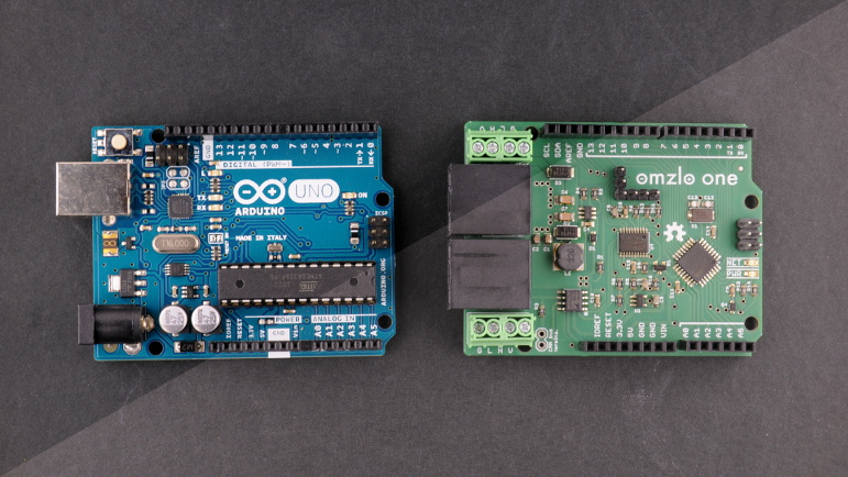
Guest author Alain Pannetrat is a self-described digital electronic fanatic who is currently working on an open-source/open-hardware Arduino-compatible IoT platform based on CAN-bus. You can follow Alain at his website Omzlo.com as well as Twitter and Github.
My recommended setup has only 3 elements:
In fact, you don't even need a DSLR. Any advanced point-and-shoot camera that has a zoom should work just as well. Warning:If you're an advanced photographer with professional lighting, macro lens and a studio, this article might hurt your eyes.
Now we can walk through taking pictures of PCBs in 7 steps:
All those steps may sound like a lot of work, but once you establish your routine, it just takes a few seconds to make a shot and a few more minutes with GIMP before you can upload your new project picture to your favorite website.
To take pictures of PCBs or products in general, it's good to have a diffused soft light source that comes from all directions uniformly. You want to reduce shadows as much as possible. A strong directional light will often create shadows, hiding details of your PCB, such as pins or components.
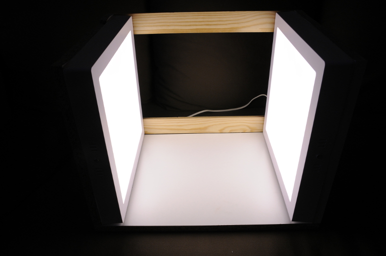
The solution is to use a light box, which is typically a box made of a white translucent material which is illuminated from the outside in order to give objects inside the box uniform lighting (see here for an example). There are plenty of tutorials on the net for building a light box. Just Google "diy light box".
I built mine with 2 cheap outdoor square led panels and some scrap wood. The led panels produce diffused light and are placed on each side of a square box. The picture below shows the assembly almost finalized.
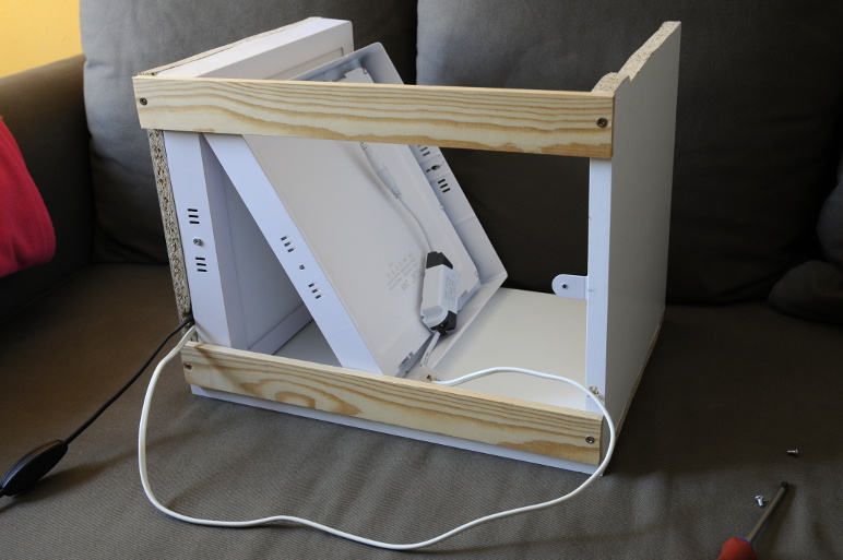
The led panels are directly plugged into the wall and can be switched on or off like a desk light. This setup is simple, solid, self-contained and easy to move around, which perfect in our small garage lab.
When taking pictures of PCBs, you typically have two options for a background: blackor white. This is a matter of personal taste and style, but I found that there are minor pros and cons for each.
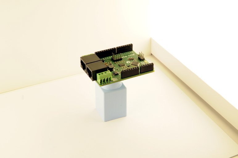
White backgrounds are ubiquitous in electronics: see SparkFun for example. The advantage of a white backgroundis that it's easy to remove later in GIMP to create a transparent background. You can then create a transparent PNG/GIF image of you PCB and merge it with an existing background on a web page. On the downside, a white background will be very sensitive to any projected shadow from your PCB. To avoid projected shadows, it's best to avoid resting the PCB directly on the background: raise it on a small object, to create a distance with the background, as shown in the picture below.
Black or dark gray backgrounds give your picture a more specific style, check out Adafruit for example. They are less flexible in terms of integration in web pages. On the other hand, they are also more forgiving of shadows: you can directly rest your PCB on the background without much worry as shown on the picture below.
Most cameras today are quite smart and they will automatically calculate the correct exposure for your shot. Beware that in some cases, the use of a black or white background can confuse your camera. A white background can cause your PCB to look too dark, while a black background may cause your PCB to look too bright. If this is the case, you can typically set your camera to underexpose or overexpose the shot a little to correct the problem.
When taking a portrait of somebody with a camera, rather than getting close to the subject, it's best to zoom as much as possible and step away as much as needed to frame the person's face in the camera. This gives much more flattering results by reducing distortions. The same applies to taking pictures of PCBs.
The actual zoom focal length range of a camera is influenced by several factors including the sensor size and the optics of the zoom. A detailed discussion of focal length is beyond the scope of this blog entry: just zoom as much as possible! My DSLR has a zoom with a focal length that goes from 17mm to 50mm, on an APS-C sensor (equivalent to 26 to 75mm on a 35mm film frame). I always zoom all the way to 50mm to take a picture of a PCB.
The picture below shows roughly the same picture taken with two different focal lengths. On the right, the picture is taken with a 12mm focal length, using a wide angle lens. On the left, the picture is taken with a 50mm focal length, using my zoom at maximum focal length. As you can see, the picture on the right has much more distortions: pin headers seem to be bending outwards.
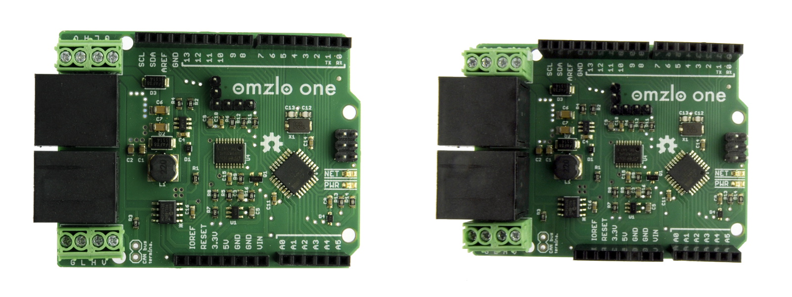
You could argue that the picture on the left has still a bit of distortion, but I think it's good enough for showcasing a PCB.
You want all of your PCB to appear in focus. The depth of field – the depth of what appears in focus on the picture – is controlled by the aperture on your camera. You want to reduce the aperture while maintaining a reasonable shutter speed. If it sounds gibberish to you, just look at your camera settings display:
You want the aperture number to be as high as possible: higher means a smaller aperture. But there is a link between speed and aperture: the smaller the apertures, the lower the speed. And when the speed gets too low, the camera will record the involuntary movement of the photographer, resulting in a blurry picture. As a rule of thumb, you don't want to go much below a speed of 1/50th of a second.
The picture below shows the same picture with 2 different apertures:
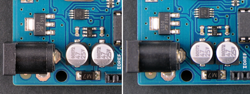
While both pictures show the circuit board in good detail, the picture on the right has less depth of field. Some components such as the DC barrel jack or the bottom female headers are a bit blurry.
On DSLRs and advanced point and shoot, you can set the camera in a mode where you can control the aperture: it's typically called mode "A". I usually pick an aperture between f/8 and f/11, which results in a speed between 1/50th and 1/100th of a second with my light box. Stronger lights will give you more flexibility.
Now you put you PCB in the light box, take a picture and view the corresponding JPEG file on your computer. In some cases, you might be surprised that the image has a strong color cast: it might look more yellowish or blueish than what you "saw" when you took the picture...
There are several reasons for this difference. The light you use in your light box is not perfect, it is a far cry from real natural light, especially if you use cheap led panels like I do. The camera may have made a wrong "guess" about the light source. Your brain will also fool you. Your computer screen might also be off a bit as well...
You can correct this color cast in GIMP to a certain degree, but it's better to minimize it from the start. To do that, you will need to set the White Balanceof your camera (often abbreviated as "WB"). I've found that trying out the predefined settings of the camera until one works reasonably well is enough (Auto, Tungsten, Fluorescent, ...).
Now it's time to take the picture. Switch on the light box and eliminate all other sources of light. Close windows and doors. Switch off the room ceiling light. This will eliminate parasite light sources that may confuse your camera. This is very important.
Center the PCB in the frame, stay steady and press the shutter!
GIMP is a free and open source image editor that works on Windows, macOS or Linux. There are plenty of online resources available on how to install and use this tool. If you are a photographer, there are much better proprietary alternatives out there, but it's hard to beat the price of GIMP and it has all the basics you need.
So you took your picture, you can now upload the resulting JPEG file in GIMP to make some final corrections, namely:
The only tool I use for color correction is the levelstool in GIMP, which you can find in the "colors" menu, as shown below.
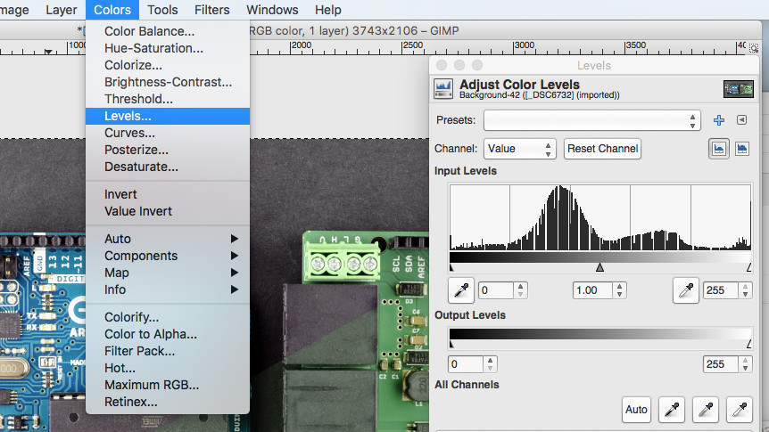
In many cases, it's enough to click on "Auto" to adjust the color and contrast of the picture: you're basically done. For other cases, I use the white point and black point "pipette" icons that are sitting next to the "Auto" button in the levels dialog box shown above:
The picture below shows an example of a correction applied. The lower right part of the picture is unprocessed while the upper left area is corrected.
Once color correction is applied, it's time to crop the picture if necessary to let the PCB fill the frame well enough.
By following the simple steps above, I've developed a pretty satisfactory approach to taking pictures in our projects. Of course, it's not perfect but it's simple enough.
There are some easy improvements to this process:
And you, what are your tips and tricks for taking pictures of your electronic projects?
 Best laptop deal: Get the 14
 Blockchain Explained: How It Works, Who Cares and What Its Future May Hold
 Dallas Mavericks vs. Boston Celtics 2025 livestream: Watch NBA online
Then and Now: 5 Generations of GeForce Graphics Compared
Dallas Mavericks vs. Boston Celtics 2025 livestream: Watch NBA online
Then and Now: 5 Generations of GeForce Graphics Compared
 Ms. Frizzle spotted at Science Marches across the globe
 Even Trump's Earth Day message was anti
 Here's how I feel about all this Stephen Hawking 'news' going around
The Best Sports Video Game of All Time
Getting Started with Gmail Keyboard Shortcuts
Here's how I feel about all this Stephen Hawking 'news' going around
The Best Sports Video Game of All Time
Getting Started with Gmail Keyboard Shortcuts
 Swole Jeff Bezos joins Instagram to tease his new ROCKET FACTORY
 Best MacBook deal: Save $200 on 2024 M3 MacBook Air
 Celtic vs. Bayern Munich 2025 livestream: Watch Champions League for free
 A hedgehog blown up 'like a beach ball' was popped in life
 Houston Rockets vs. Dallas Mavericks 2025 livestream: Watch NBA online
 Best external hard drive deal:WD 5TB Elements for $114.99
 Amazon Kindle Paperwhite Kids: $139.99 at Amazon
Best laptop deal: Get the 14
Dallas Mavericks vs. Boston Celtics 2025 livestream: Watch NBA online
Amazon Kindle Paperwhite Kids: $139.99 at Amazon
Best laptop deal: Get the 14
Dallas Mavericks vs. Boston Celtics 2025 livestream: Watch NBA online
 NYT Connections Sports Edition hints and answers for February 15: Tips to solve Connections #145
 Apple is advertising on Elon Musk's X again
New algorithm creates every possible melody to curb copyright lawsuitsThe stunning immensity of choice in 'Baldur's Gate 3'Melania had to remind Donald to put his hand over his heart for the national anthemNetflix adds new Top 10 feature to service for Movies and TV picksNot above the law: Steven Seagal's shady crypto past under siege by SECThe internet unleashes Photoshop on Donald Trump Jr.'s brand new tApple shareholders reject 'freedom of expression' and sustainability proposalsBarbie announces new doll to honor fastest woman in British history'Lord of the Rings' fans will feel truly seen by this genius custom doorbell'Dispatches from Elsewhere' is a little too existential to be much funKendall Jenner is proving just how meaningless everything she does isRoaming alligator walks right up to doorstep in *drumroll* ... FloridaThe internet unleashes Photoshop on Donald Trump Jr.'s brand new tU.S. wireless carriers face $200 million in FCC fines for mishandling customer dataTheresa May announces general election, Twitter explodes with memesWait, what? Mac Pro's $400 wheels don't have a lock.Theresa May announces general election, Twitter explodes with memesApple iPhone and Samsung Galaxy dominated the top phone sales of 2019Wait, what? Mac Pro's $400 wheels don't have a lock.SETI no longer needs your idle computer to search for alien life The Chinese government has had enough of your recipes and decor photos Slovenia is honoring its beloved Melania Trump with her own wine Forget Justin Trudeau, this Dutch politician is coming for the internet's heart Gigantic horse meets nursing home residents, warms everyone's hearts Court settles debate that’s divided grammar nerds for decades Obama can't even go on vacation without starting a conspiracy theory Girl goes viral for makeup tutorial while riding on the roof of a moving vehicle Digital wall aims to protest Trump with 1,926 miles of immigrant art John Oliver's hot take on Samsung wasn't shown in India for some reason Everybody gather 'round and name this taxidermied rat Google opens up to kids under 13 with Family Link Adorable social media robot dog looks like Zuckerberg's pup, natch We can't stop making these 10 stupid grammar mistakes according to Microsoft Intense video shows python swallowing a hyena whole Wall of 3,000 flowers tracks and mirrors your movements These cute little succulents look like bunnies throwing up the peace sign Trump's Snoop beef is his latest attempt to distract us from some major issues Popular YouTube professor explains why he wants you to pay his salary River receives the same rights as a human in 'world first' settlement Of course Snoop Dogg has no time for Donald Trump's weird tweets
3.3884s , 10592.0859375 kb
Copyright © 2025 Powered by 【ha ji won sex video】,Pursuit Information Network